Importance of Suction Pressure Fluctuation in Boost Applications
Suction pressure is a critical input when designing booster station applications. However, the type of suction pressure and the range available is often overlooked at the initial design stages. This often causes major issues with the design of the system resulting in higher costs, cavitation, and even downtime when failures occur. With accurate suction pressure measurements, the booster station will meet design requirements and meet the life expectancy with minimal maintenance.
First, the type of suction pressure available must be defined. Typically, a job site will have one of three different types of pressure configurations: Pressure Boost, Flooded Suction, or Suction Lift. Each configuration will dictate how the design and condition points for the station are calculated.
Boost Applications
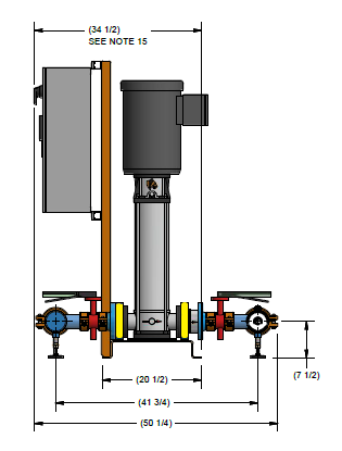
Boost applications incorporate a pressurized water source upstream of the station. The pressurized water source is typically a municipal water line. A backflow preventor is installed to stop any backflow contamination to the city water source in an event of an emergency. Backflow preventers can have a pressure drop up to 12 psi across the component depending on the design. The suction pressure reading must be recorded downstream of the backflow preventor to account for the pressure drop when designing the booster station. Figure 1 shows an example layout:
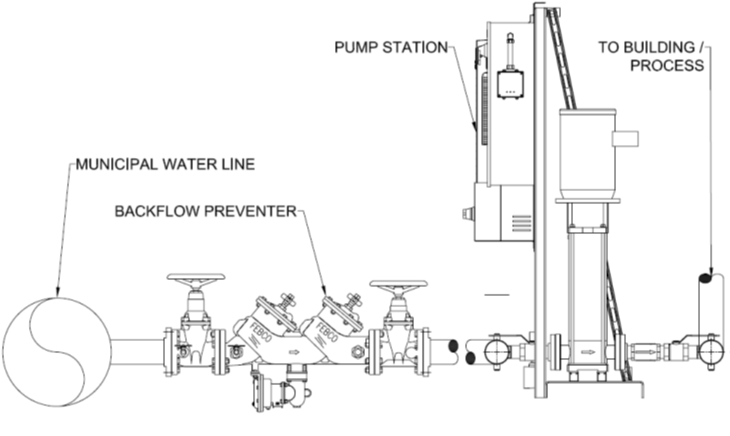 Figure 1. Boost Application
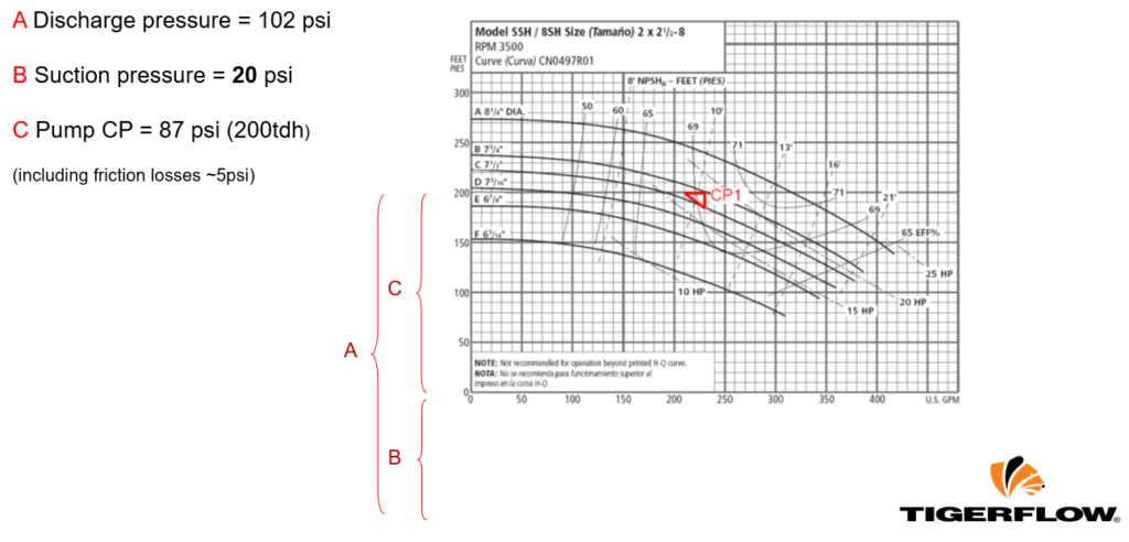
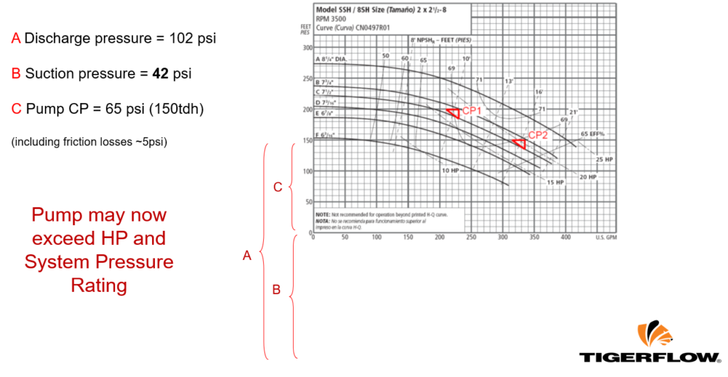
It is critically important to measure the minimum and maximum suction pressure. The magnitude of variation will decide the pump sizing for the station. For example, a job site requires 102 psi discharge pressure, and 20 psi is measured at the suction source. Therefore, the pump is sized to output 87 psi (with friction losses included) to meet the required condition point. The condition point selection is shown in Figure 2. However, if the suction pressure varies, the condition point will be shifted along the curve. If the suction pressure is measured at a different time to be 42 psi, the pump will exceed the horsepower rating in this example. The shift along the curve is shown in Figure 3.
Finally, the highest system output pressure should be calculated. This number is found by finding the Shutoff Pressure of the pump and adding the highest measured suction pressure. This is the maximum pressure the pump will output and the station components (valves, piping, etc.) must be sized for at least this requirement.
Pump Shutoff Pressure + Max. Suction Pressure < Station Pressure Rating
Figure 2. Condition Point at 20 psi Suction Pressure
Figure 3. Condition Points Compared
TIGERFLOW specializes in pumping stations’ engineering designs to accommodate different challenges, including fluctuating suction pressure.
To learn more about TIGERFLOW’s design, contact your local representative using our Rep Locator.
For over thirty years, TIGERFLOW Systems LLC has been an industry leader in manufacturing engineered packaged pumping systems. Based out of Dallas since 1985, TIGERFLOW was founded to design, manufacture and ship the best-packaged system for many different markets – Plumbing, Fire, Heating Ventilation, and Air Conditioning, Irrigation, Municipal, and Industrial.


